Camera
Camera
View > Camera > Properties
The Camera provides a focal point for the scene from which to view the parts from different viewpoints.
The Camera provides a fixed point with a line of sight determined by a target point.
A perspective view with a defined view angle of the parts can be maintained during scene rotation.
The Camera properties dialog also controls the rendering modes for Wireframe, Hidden Line, Draft and Quality rendering.
In the section below, the positional points which define orientation of the camera are discussed and demonstrated.
Position and Orientation
Camera Centered
This option allows the camera to be located in the center of the scene, positioned such that objects in the scene revolve around a fixed focal point when using camera movement tools such as :
-
Walk
-
Slide
-
Turn
-
Roll
-
Examine
When this option is disabled, the rotational focal point is performed around the target.
Perspective View
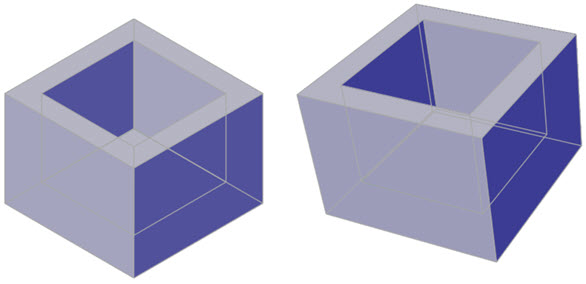
This is a viewpoint which provides a depth perspective, tilting the view slightly to provide a foreshortened field of view. In the example below left, the box is viewed from an Isometric South East viewpoint, with Perspective disabled.
In the image below right, the box is viewed from an Isometric South East viewpoint with Perspective enabled.
Tip
The Workplane is a reliable visual indicator of whether Perspective view is enabled or disabled as it aligns itself to the view.
Position
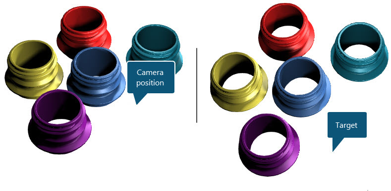
This is the current X-Y-Z positional location of the camera in the editor.
Target Point
The Target Point is the direction of the line of sight, orientating itself from the camera position to the target point. In the example below, the orientation of the view is aligned to the target point.
The UP Vector
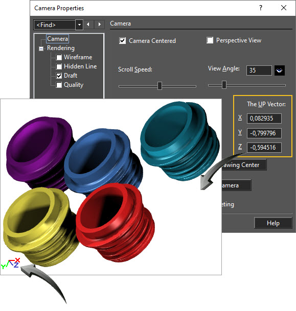
This is the positive or negative value determining an up or downwards orientation of the camera. The values of the X-Y-Z vectors should be positive if the part is being viewed in normal up-down orientation.
This is helpful when viewing objects with similar top and bottom shapes as it enables the correction of a view by adjusting the positive or negative UP Vector values.
In the example below, objects are viewed upside down but the objects' shape make this difficult to immediately distinguish. The WCS shows a 'negative' orientation of the Y-Z axes which are reflected in the UP Vector values of the Camera Properties.
Tip
The WCS icon is a reliable visual indicator of whether the view is in a positive or negative orientation. Enable the WCS icon by navigating to Options > Preferences > Show WCS.
Worked Example
- Draw any 3D object in the editor or download and open the Camera drawing.
- All objects in this design are stored as separate parts in the Blocks palette should you wish to experiment with multiple cameras.
- Follow the above instructions to experiment with various Camera options.
See Also