Selector Settings
Classic Selector
Right-click in editor > select 2D or 3D Selector Properties
The Selector Shell is attached when an object is selected using the Select tool.
The Selector Shell allows in-place modification and manipulation by using the handles, the rotator bar and the reference point.
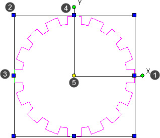
The Classic selector provides a selector shell with the following properties :
- X-Y-Z axis handles and labels.
- Handles at each corner for resizing the selection.
- Handles at each midpoint for stretching the selection.
- Rotator bar and green handles used for rotating the selection.
- Yellow reference point used to move or copy the selection.
The Classic selector can be set to adapt to the following conditions :
- 2D Objects
- 3D Objects
- 2D or 3D Objects dependent upon the object selected.
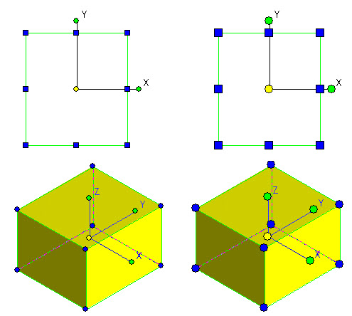
In the example below, the selector is set to create a selector shell bounding box suitable for a 2D object. The 2D profile of the object is selected.
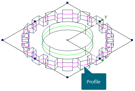
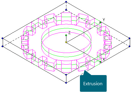
The example below shows the selector shell bounding box suitable for selecting a 3D object. The 3D extrusion is selected.
NOTE : When the Selector Properties option is set to 2D/3D Depending on Selected Object and Space Mode, the selector shell adapts accordingly to either a 2D profile or a 3D object.
Toggle 2D/3D
Right click in the editor > Select Toggle 2D/3D to toggle between 2D and 3D selector modes.
(The Toggle 2D/3D icon at the base of the editor can also be used)
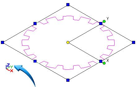
The Classic Selector can be toggled between 2D and 3D mode when selecting either 2D profiles or 3D objects.
In the example below, the Selector properties are toggled between 2D, below left and 3D, below right.
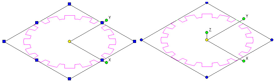
NOTE : The advantage of setting the selector to 3D when selecting 2D profiles is that rotation through a 3-dimensional axis is facilitated.
Handles and Axis Marker size
Right-click in the editor > Selector 2D or 3D Properties > General > Mark Size
The Mark Size (handle) can be increased or decreased depending on user preference.
This option adjusts the handles and axis markers of the 2D or 3D Selector Shell.
This allows the user to personalize how the selector shell features are displayed when selecting an object.
In the illustration below left, the default mark size for the selector shell features is shown.
In the illustration below right, the default mark size is increased to 6.
Example
- Draw a 2D profile or 3D object in the editor.
- Right click in the editor and select 2D or 3D Selector Properties (depending on the current mode)
- Select General > Mark Size and deactivate the Calculate Automatically checkbox.
- Input the preferred size. In the example above right, the custom size is set to 6 pixels.
- Select either the 2D profile or the 3D object to view the handles and axis marker size.
NOTE : When the Mark Size is set to Calculate Automatically, the size is set to a default setting, irrespective of the object's size or the current zoom magnification.
Axis Labels
Right-click in the editor > Selector 2D or 3D Properties > Selector 2D > Show Axis Labels
The option to Show Axis Labels is available in the Selector 2D page in the Selector Properties dialog.
When enabled, it displays the XY axis labels in accordance with the World Coordinate System, shown by the arrow below.
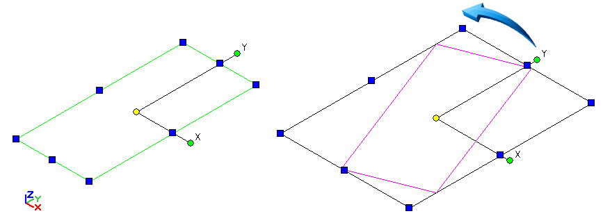
In the illustration below, the object is selected in an Isometric view, aligning the axis label to correspond to the WCS.
The orientation of the X-Y axis labels maintains alignment with the current WCS during rotation. The example below shows how the axis handles and labels maintain orientation to the WCS when the object is rotated.
See Also