SKetch Tools
Although there are multiple variations of 2D geometric objects which can be created in the workspace, these roughly fall into two categories :
- 2D Line geometry
- 2D Circle geometry
2D Line Geometry
Drafting & Annotation Menu | Home | Draw
This consists of line tools such as single lines, multiple lines (polylines), polygons, rectangles etc.
All 2D line geometry can be created in the workspace by means of inputting accurate geometric and spatial information.
Any line can be drawn according to length and angle dimensions using polar or rectangular coordinates.
The dynamic input fields allow implied length and angle tracking providing a visual guide of the spatial coordinates of a line.
Closed line objects such as Polygons and Rectangles are created either using the dynamic input fields at the cursor, or by inputting specific length and angle values into the Command line.
2D Circle Geometry
This consists of circle tools such as circles, arcs and ellipses.
All 2D circle tools provide options to generate these objects according to specific criteria such as radius, diameter, tangential connections etc. For example, a circle can either be drawn from a center to a radial point, from 2 points on the diameter or by connecting 2 tangential points to other circles or lines.
The dynamic input fields create implied dimensional information, such as radius, diameter etc or this information can be input into the Command Line.
Take Note
All 2D Sketch Objects can be selected and modified using Grips to adjust their physical (layer, color, linetype) properties, or their geometric properties. The Properties2D Drawing & Annotatio> View> Palettes> Properties. palette is used to change these properties.
 Video Tutorials
The video tutorials below can be referenced during this Session.
Technical Sketch using Line Geometry & Annotation
Technical Sketch using Circle/Arc/Tangential Geometry
Sketch Object Information
Once the sketch object is drawn, information about this object can be obtained by selecting the object so that Grips are attached to the object. A quick properties selection box can be displayed providing information associated to the selected object by double-clicking onto the object and viewing the information in the Quick Properties palette.
In cases where multiple objects are selected, these are provided in the Properties palette, shown below. In the illustration below, the information supplied is context-sensitive, for example, by selecting the Circle in the Properties palette, information associated only with the circle will be displayed.
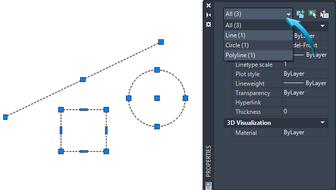
Properties palette showing the selected object
The geometry of an object can be adjusted using the Properties or Quick Properties palette. In the example below, the circle is selected by double-clicking onto it, and the radius value can be updated.
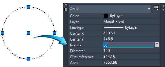
Updating the radius value in the Quick Properties palette
When Sketch objects are input into the workspace, they can be manipulated and modified (erased, moved, rotated, stretched, scaled), or duplicated (copied, mirrored, offset, arrayed) using the modification tools, discussed and demonstrated in greater detail in Foundation | Object Handling.
Sketch objects which are input into the workspace can also be constrained. This method controls the spatial and geometric conditions around an object and is discussed and demonstrated in greater detail here.
related topics
Construction Objects
Construction objects are used as temporary objects in cases where simple geometry is required.
Construction lines are created on the current layer and respond to the changes of the layer property such as color, linetype, transparency, etc.
Certain snap modes can be used with construction entities. Nearest, intersection, tangent and perpendicular snap modes can be used. Endpoint snap modes cannot be used with construction entities as they are of infinite length.
Frequently used Construction objects are :
Construction Line
This produces a construction line of infinite length, allowing options of horizontal, vertical, angle, bisect, offset to be selected.
Ray
Provides multiple lines at selected angles radiating from a common point.
Calculator Tools
Dynamic Input Fields
The Dynamic Inputfields are useful for inputting basic calculations during a command sequence. For example, an offset distance can be halved by inputting the 'value / 2' shown in the illustration below.
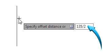
Creates an offset distance of 67.5
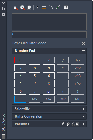
Calculator Palette
QuickCalc Palette
Drafting & Annotation | View | Palettes | Calculator | Right click in editor, select QuickCalc
The calculator palette, shown below, is an accessible calculator tool which performs a range of scientific, mathematical and geometric functions.
Calculations can be performed in the calculator, then pasted into the command line when used transparentlywithin a command sequence.
Quick Calculator. View > Palettes > Quick Calculator [right click in editor, select QuickCalc]
The Quick Calculator performs unit conversion of lengths, areas and volumes from standard units of measurement and also calculates formulas and variables. In the example below, the simple formula (117-32)/2 is input into the field. The resulting value is returned, shown below.
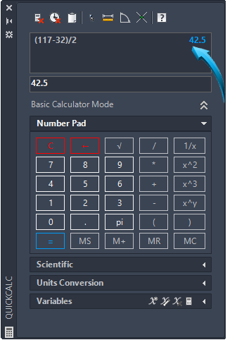
Inputting a basic formula into the QuickCalc
Paste Value to Command Line
Information calculated by the calculator palette can be pasted into the command line during a drawing sequence.
In the example below, a line length is being calculated using the calculator. This computed value is then pasted into the command line and the drawing sequence is uninterrupted.
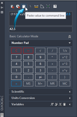
Calculating and pasting a value into the command line
Parametric Objects
Constraints
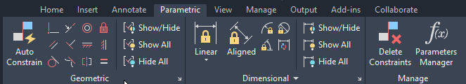
Drafting & Annotation | Parametric
Dimensional and geometric constraints form a principal component of conceptual design.
Design intent is best captured by creating an approximate shape of the intended profile. By applying geometric and dimensional constraints to the lines and curves, spatial and geometric relationships can be created between objects which are updated when the dimensions are changed.
The Parameters Manager parametrically constrains the geometry of the sketch to specified conditions, eg: perpendicular; parallel, equal radius, tangent. etc. These are referred to as geometric constraints and are displayed in the ribbon panel above.
Dimensional constraints apply linear, angular, diametric and radial constraints to objects to define measurement and spatial relationships. These are controlled through the standard dimensioning features.
Auto-Constraints can be automatically added to a sketch when their geometry is implied. For example, when drawing a simple rectangle, geometric constraints are applied to make the opposite lines of the rectangle parallel to each other, makes coincident the end points of the lines, and constrains all connecting angles to 90º, making the lines perpendicular.
Example
A rectangle will be constrained to specific measurements.
AutoConstraints will be added so as to maintain geometric integrity of parallel and perpendicular conditions.
A circle will be added, then the diameter constrained to a specific measurement.
The circle will be moved parametrically so that it is in the center of the rectangle.
Take Note
Dimensions shown grayed out in the illustrations are for illustrative clarity only.
Geometric and Dimensional Constraints are discussed and demonstrated in greater detail here.
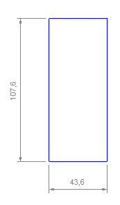
In this example, a quick rectangle to the approximate dimensions shown below is drawn.
This rectangle is exploded reduces a compound entity to its individual components. For example, a rectangle, when exploded comprises 4 single lines instead of a single entity so that all four sides are separate objects. Select the Rectangle, then go to Drafting & Annotation | Home > Modify > Explode.
Geometric Constraints
Auto Constraints are then added to this sketch so that obvious geometric conditions such as parallel  and perpendicular
  conditions are maintained. Select Home > Parametric > Auto Constraints and use a selection window to select the 4 lines. Press enter. The result is shown below.
By positioning the cursor/crosshairs over the constraint marker, the type of constraint is shown, similar to the Perpendicular constraint below.
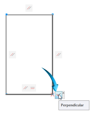
Auto Constraints added to sketch. Constraint markers identified.
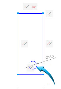
A circle with the approximate diameter and spatial location to that shown in the illustration below is drawn. No attempt is made at dimensional accuracy at this stage.
Dimensional Constraints
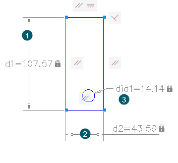
Parametric Dimensional Constraints are then added to the sketch , shown below.
To do this, select Home > Parametric > Dimensional > Horizontal/Vertical and apply endpoint to endpoint dimensions in the sequence shown below. Press enter each time to add the dimensional constraint to the Parameters Manager palette. Use the Diameter constraint to add a constraint to the circle, shown below.
Parameters Manager
Drafting and Annotation | Home | Parametric | Manage | Parameters Manager
When dimensional constraints are applied to a sketch, such constraints are added to the Parameters Manger palette, shown below.
Select Home > Parametric > Manage > Parameters Manager to display the information in the editor, shown below.

Parameters Manager showing 3 dimensional constraints
This is the means by which the dimensional constraints can be managed, either by updating the value or by inputting a conditional formula.
The measurement of the rectangle will now be adjusted so that the length (d1) is 100 and the width (d2) is 50. The circle will be adjusted so that the diameter is 15.
Left click onto the Expression value of the d1 constraint shown by the pointer below then update the value to 100.
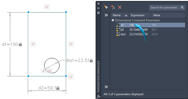
Length (d1) constraint updated to 100
As can be observed from the illustration above, the vertical dimensional constraint, has updated to 100.
Repeat this, updating the (d2) constraint to 50 and the (dia1) circle constraint to 15. The result is shown below.
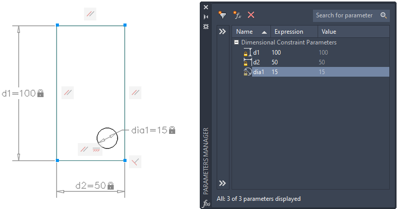
Updating the (d2) and (dia1) constraint
Formulas & expressions
By inputting a formula into the Expression field of the Parameters Manager, the spatial coordinates of the circle can be constrained such that the center of the circle is positioned at exactly half the dimension of the width (d2) dimension.
To achieve this, an intermediate dimensional constraint has been added showing the distance from the left edge of the rectangle to the center of the circle, shown by the arrow below.

New horizontal constraint (d3) added showing distance from left edge to center of circle
By inputting the formula shown by the arrow below into the expression field, it indicates that the measurement of d3 (the distance from the edge of the rectangle to the center of the circle) will be half the measurement of d2 (horizontal measurement)
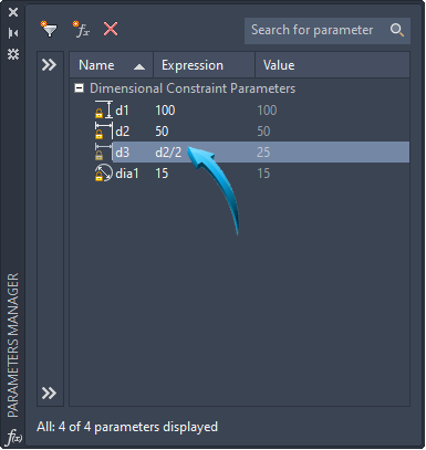
Inputting an expression as a formula
It can be observed that the measurement of d3 is now exactly half (25) the measurement of d2 (50).
Constraint Integrity
This constraint will now be maintained no matter how much the dimension of d2 (width of the rectangle) is changed as shown from the illustration below.
For example, it can be observed by the arrow in the illustration below that the value of d2 has been changed to 80. The horizontal dimension has been concurrently updated in the sketch and the position of the center of the circle has retained its constrained position, being exactly half the width dimension (d2)
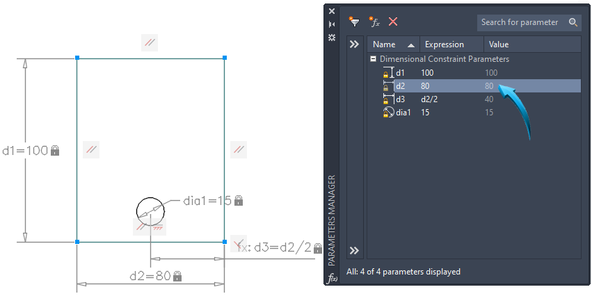
Value of (d2) updated but circle retains its constrained position to half the value of the width
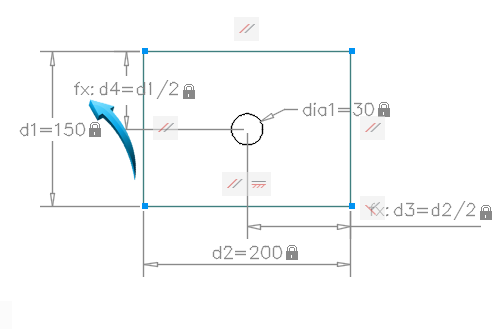
By adding another vertical dimensional constraint showing the distance from the top edge of the rectangle to the center of the circle (d4) , the value in the expression field can be similarly expressed such that it is fixed and constrained to exactly half the overall height (d1) measurement, shown below.
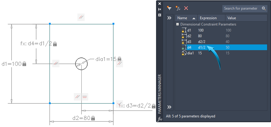
New d4 dimension constrained to half the overall length (d1)
The position of the circle will remain fixed and constrained in the 'center' of the rectangle irrespective of the overall (d1 and d2) dimensions of the rectangle, shown in the illustration below.
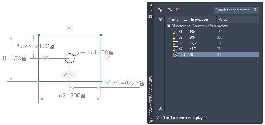
Overall (d1 and d2) dimensions changed, circle retains its position in the 'center' of the rectangle. Circle diameter updated to 30, retains its position.
Take Note
A dimensional constraint shown prefixed by fx: indicates this constraint is the subject of a formula input into the Expression field of the Parameters Manager, shown below.
Constraint prefixed with fx: indicates a constraint condition
Additional Resources
Additional Information on Geometric & Dimensional Constraints
Video Tutorial of Constraints & the Parameters Manager
