drafting Settings
Drafting settings apply standardized settings to the workspace. These settings affect the appearance and functionality of the workspace.
New Drawing from Template
A template is used to facilitate consistency between drawings and to prevent the necessity of creating commonly used layers, styles and formats.
A variety of templates can be created to suit user-defined applications, for example when switching between architectural-type and mechanical-type drawings.
Standard templates are provided with each AutoCAD product and can be adapted and modified to suit user requirements in terms of layers, linetypes, precision units, fonts, dimension styles etc.
Example
In this example, a new drawing will be selected from a pre-defined template. This template will then be fine-tuned to suit a metric-mechanical environment.
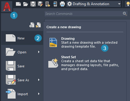
From the AutoCAD start menu, shown in the top left corner of the editor, select New > Drawing. This will allow the user to select the preferred template.
Starting a New Drawing from a Template
Select the template Tutorial-mMfg.dwt (metric-manufacturing) shown below.
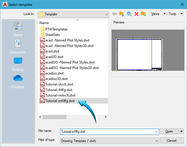
Selecting a metric-manufacturing template
The drawing template will open in the Paper layout, shown below. This shows the outer edge of the page and a pre-inserted title block. This is the space from where a viewport of the drawing will be inserted from the Model workspace.
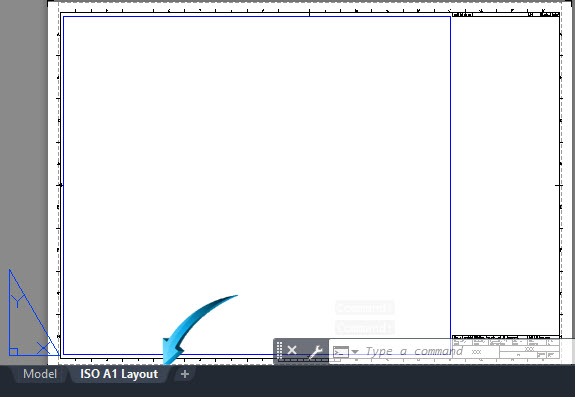
Template title block in paper layout
Left click onto the Model tab, shown below to display the model workspace of the editor.
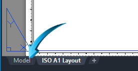
Switching to the model workspace
All sketches and drawings are drawn and produced in the model space layout at FULL SCALE, irrespective of the size of paper onto which these sketches will be printed.
It is never necessary to create a defined drafting area in the workspace as the workspace shrinks or expands to accommodate the drawings.
Saving a Customized Template
Any template can be modified or updated at any stage and saved as a new template from which new drawings can be started. For example, new layers and specific settings can be stored in a template and saved as a customized template.
example
The newly customized template will be saved to the templates folder as 2D M Student .dwt (2D Mechanical Student)
Select the AutoCAD application icon at the top left of the editor shown by point 1 below, then Save As, shown by point 2 below. Next, save this as a drawing template, shown by point 3 below.
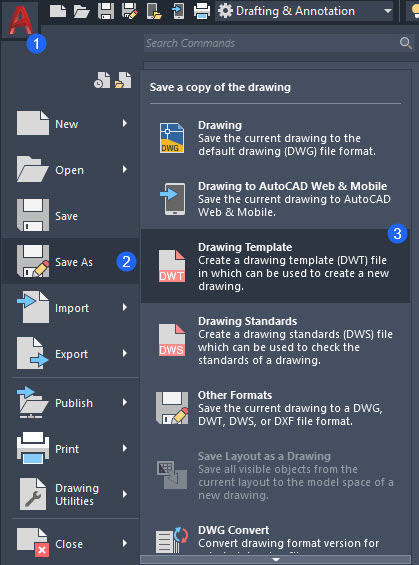
Saving the current template
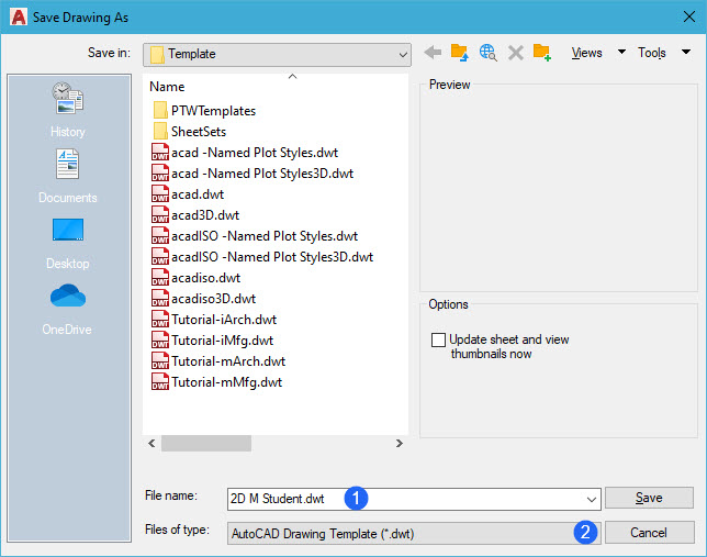
Save this file as 2D M Student.dwt (2D Mechanical Student) similar to the illustration below. Make sure the files of type is set to AutoCAD Drawing Template dwt, shown by point 2 below
Input a suitable description for the new template, then click OK to save.
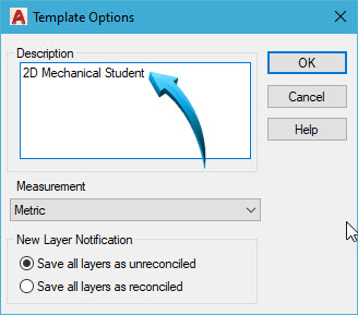
Inputting a description of the template
New drawings can now be started using the newly created template by selecting the AutoCAD Application icon at the top left of the editor, then selecting File > New > Drawing, then selecting the newly created template, shown by the pointer below.
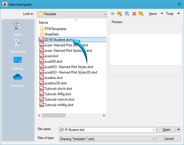
Selecting the newly created template to start a new drawing
Layers
Layers are used so that objects drawn on specific layers can be switched on or off. This controls the layer's visibility.
The accessibility of objects can be controlled by locking or unlocking a layer.
Using the layering facility within a drawing allows objects drawn on a particular layer to be controlled by name, color and linetype.
Named layers specific to a defined drawing discipline such as mechanical, architectural, electrical etc, can be standardized at the beginning of a job and these layers can be stored in a template to avoid creating similar layers in subsequent new drawings.
Any layers contained in symbols, blocks or other drawing entities which are inserted into the current drawing will be incorporated into the existing layer structure.
New layers are created using the Layer Properties palette, shown below.
When a layer is defined as current, all subsequent objects are drawn on that layer until changed by the user.
Layer Properties
Drafting & Annotation | Home | Layers
The Layer Properties palette is a multi-purpose palette which provides :
- the creation of new layers
- the renaming of existing layers
- activating a layer as the current layer
- showing or freezing a layer
- locking or unlocking a layer
Layer Status
Objects on specific layers are controlled by activating or deactivating a specific layer status. The layer status is illustrated below.
Layer A-Electrical is designated as current - all subsequent objects are drawn on this layer.
Layer A-Plumbing is designated as locked - Objects drawn on a particular layer are visible but cannot be modified when the layer status is locked.
Layer A-Walls is designated as off - when layers are switched off, they are not visible in the editor and are unaffected by changes made to associated objects.
Layer A-Windows is designated as frozen - the layers are not visible in the editor
All layers other than A-Windows are switched on - these objects are active and visible in both the model workspace and paper space layouts.
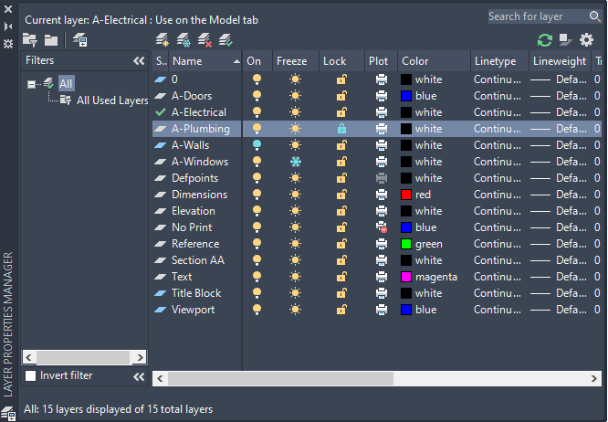
The Layer Properties palette showing the status of layers
Example
In the example, below, a model has been assembled from 3 separate parts. These parts have been drawn on their own layers to make the assembly more accessible.
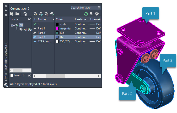
Components produced on 3 layers
Layer Transparency
Layers can have a transparency percentage to assist with the visualization of interior objects. In the example below, the layer for Part 1 has a 60% transparency. This transparency applies to all objects drawn on Part 1.
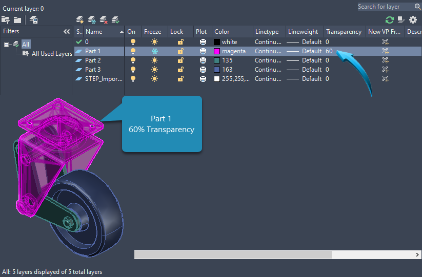
60% Transparency applied to Part 1
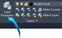
Creating a New Layer
New layers are created using the Layer panel | Layer Properties tool.
New layers can be added to the current layer structure at any stage of the design process.
Newly created layers are only available in the drawing in which they were created, unless saved in a template.
Example
A new layer called Profile will be created in the template.
The workspace menu interface is set to Drafting and Annotation.
The Home tab in the ribbon is activated.
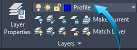
From the Layer panel, select Layer Properties, shown below.
The Layer Properties palette is displayed, shown below.
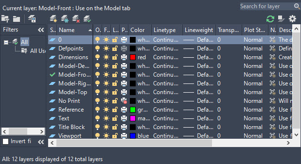
Layer Properties palette
Click onto the New Layer option shown by the pointer below, then input the name Profile in the field provided, shown below by point 1.
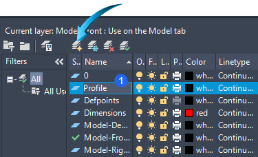
Creating a new layer 'Profile'
Change the color of the newly created layer by selecting the color block to the right of the layer name and shown by the pointer below, then selecting an appropriate color.
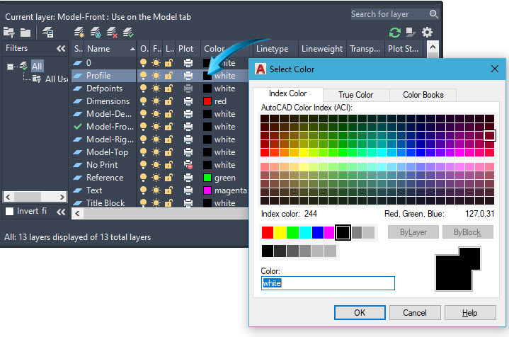
Defining a color for layer 'Profile
Take Note
Each column of a dialog box can be expanded independently. Long-press on the vertical bar next to the column name and drag to expand the contents of the column.
Activating a Current layer
A layer is defined as 'çurrent' when new objects are drawn using this layer.
With the Profile layer selected, select the Set Current option, shown by the pointer below. Notice the check mark next to the layer name when a layer is activated as the current layer.
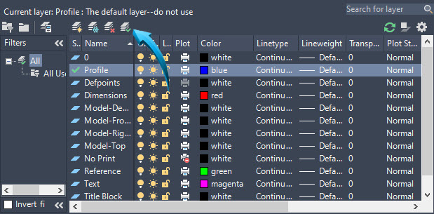
Activating the layer 'Profile' as the current layer
Close the Layer Properties palette by selecting the Close icon at the top left corner of the dialog box. This palette can be reactivated by selecting the Home > Layer > Layer Properties.
The Layer panel will now display 'Profile' as the current layer, shown below. All subsequent objects will now be drawn on this layer, assuming the properties of the currently activated layer.
'Profile' shown as the current layer
Layer Filters
Layers can be grouped into inter-related categories using Layer Filters.
This is usually done to provide quicker access to layers relating to a specific area in a drawing, such as an architectural layout, or the components of an assembly.
Layers can be added to and removed from filtered layer categories at any stage without deleting the layers or their associated objects from the drawing.
In the example below, Parts 1-4 will be grouped together to create a layer filter called 'Assembly'
The first layer is selected, then the remaining layers are selected by holding down the keyboard Shift key.
Select the Layer Filter option shown by point 1, then input the Layer Filter Property name, shown by point 2 below.
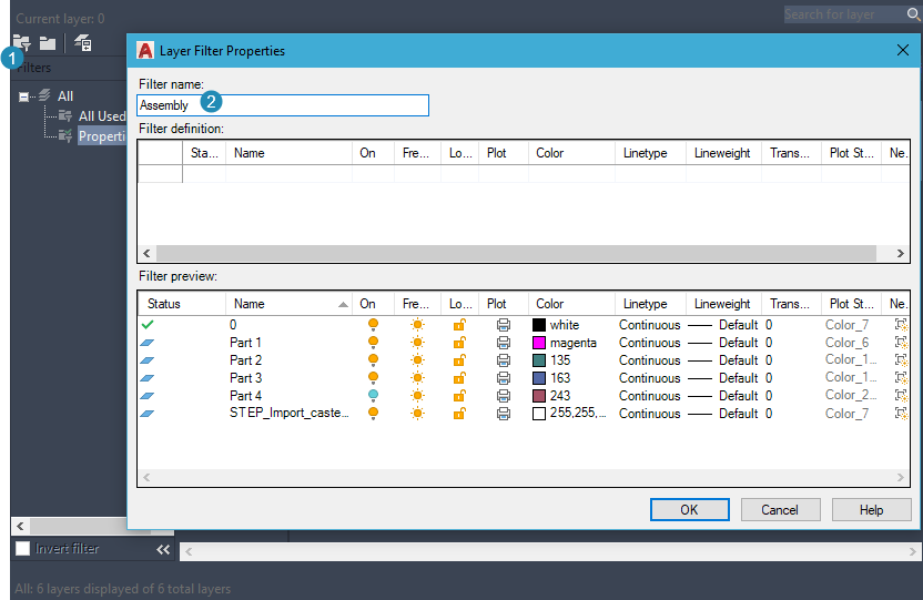
Creating a Layer Filter of Parts 1-4
Specific actions can now be associated with this group by right-clicking onto the new Filter, shown below.
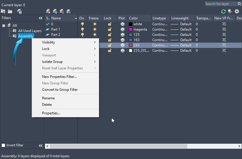
Creating a Layer Filter 'Assembly'
Hiding/Isolating Objects
Status Bar | Isolate Objects
This display tool allows objects which are drawn as specific parts to be temporarily isolated or hidden from view.
This is effective when producing a design composed of several composite parts or to view interior regions of parts.
When selecting the Isolate Objects option, only the selected object or group of objects is displayed in the editor, with all remaining objects being temporarily hidden. The End Object Isolation tool restores the display of all entities in the drawing.
The Isolate/Hide Objects tool functions for both 2D profiles and 3D parts, and single or multiple objects can be selected to be Isolated or Hidden. Objects drawn on multiple layers can also be selected, provided such layers are not locked.
When the End Object Isolation tool is selected, all previously isolated (displayed) or hidden objects are restored to the editor, irrespective of the current view.
The Isolate/Hide Objects tool functions independently from layer control options such as Freeze etc.
Hide Objects
In the example below, the Hide Objects tool is activated. Part 1 is selected, shown below left.
Part 1 is temporarily hidden in the editor, allowing greater visibility of Parts 2 and 3, shown below right.
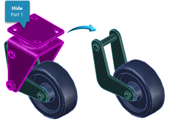
Part 1 hidden
Isolate Objects
In the example below, the Isolate Objects tool is activated and Part 2 is selected, shown below left. Parts 1 and 3 are hidden in the editor, showing only Part 2.
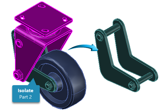
Part 2 Isolated
End Object Isolation
The Isolate Objects tool in the Status Bar is activated, shown below when objects are hidden or isolated in the editor.
To restore the visibility of objects in the editor, the End Object Isolation tool is used. This restores all hidden objects in the editor.
GRIPS
Grip Handles
Grip 'handles' are used to select an object or group of objects for quick and convenient in-place modification or manipulation purposes.
Grip handles are attached to an object when blue handles appear at strategic points of geometry on an object. No command is necessary to attach grips to an object.
When Grips are applied to a selected object, they are done so at each vertexThe endpoint of a line, or junction of 2 intersecting endpoints. and at the midpointThe point of geometry at the exact midpoint between two vertices (endpoints) of lines. These Grips provide a convenient handle by which to manipulate or modify the selected point or the entire object.
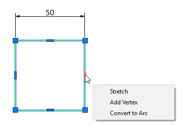
When the cursor is positioned over a grip handle, it changes color, and implied options are automatically presented, similar to the illustration below.
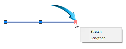
Stretch Vertex
Grip handles are dragged dynamically and a data field is displayed to provide feedback on the updated feature. In the example below , the Grip is selected shown by the pointer. This allows the rectangle to be stretched dynamically. In this example, the line will stretched by 20 towards the right.
To stretch the object by the selected grip handle, long-press the grip, then drag towards the right. The data field shown alongside the cursor will dynamically update to show the length and angle measurement, shown below.
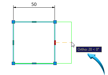
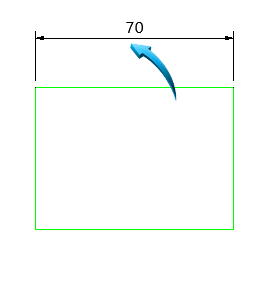
Left click when the data field shows a length of 20 and an angle of 0, shown above. The dimension associated to the rectangle will be correspondingly updated, shown below.
remove Vertex
A vertex can be added or removed to modify the shape of the object. In the example below left, the top right grip is selected for removal to produce the result shown below right.
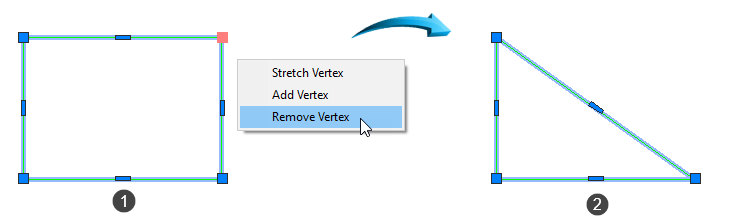
Removing the top right vertex
Add Vertex
A vertex can be added to modify the shape of an object. In the example below left, the top middle grip is selected and the Add Vertex option is selected. A vertex point is added to the middle of the line, allowing the object to be reshaped, shown below right.
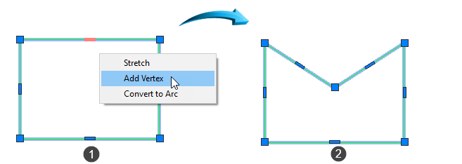
Adding a vertex to the midpoint of the top horizontal line, shown above left
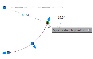
Convert to Arc
A line can be converted to an arc by positioning the cursor over the grip and selecting the Convert to Arc option, shown below left.
This converts the line to an arc, allowing the apex of the arc to be controlled to reshape the object, shown below right.
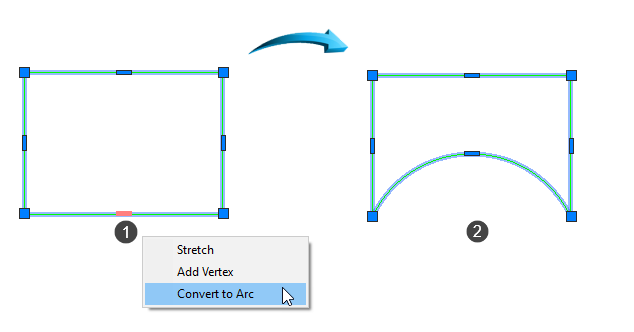
Converting the line shown by point 1 to an Arc
Circle Radius
When Grips are attached to a circle, the radius can be changed by inputting the value into the dynamic input fields, shown below. In this example, the radius of the circle has been changed to 40.
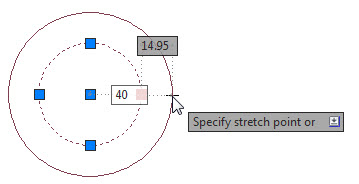
Grips used to change the radius of a circle
Arc Radius
When Grips are attached to an arc, the radius, of the arc, as well as the circumferential radius of the arc can be adjusted, shown below.
Grips used to change the radius of an arc
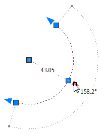
Arc Length
Grips attached to an arc can also be used to adjust the arc length by redefining the start and end point of the arc, shown below.
Grips used to change the arc length by relocating the start/end point
Grips are canceled using the keyboard Escape key.
Accessing the Properties Palette
When grips are attached to an object, the Properties palette can be accessed by selecting an object to attach grips, then right-clicking anywhere in the editor and selecting Properties from the context menu, shown below. In the example below, the geometry of the circle such as the radius or diameter can be updated.
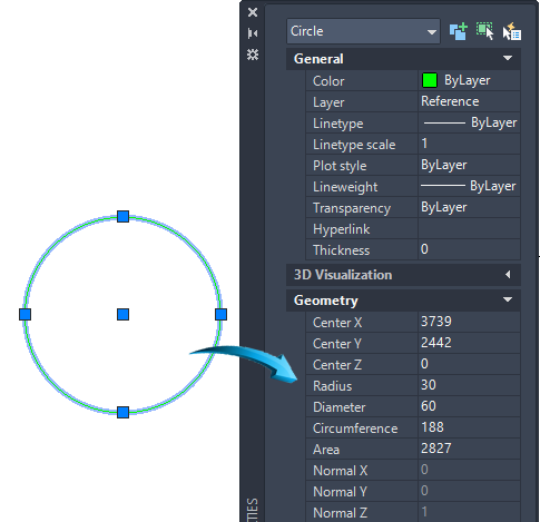
Using grips to access the Properties palette. Object geometry can be viewed and modified.
The Properties palette is a context-sensitive feature that is used to view or change any physical (layer, color, linetype etc) or geometric (length, angle, radius etc) characteristic of an entity.
The properties of solid objects such as solid primitives, surface and mesh objects can be modified in the Properties palette by selecting the object with the grips. In the example below, the geometry of a solid primitive Box is shown in the Geometry panel and can be updated here.
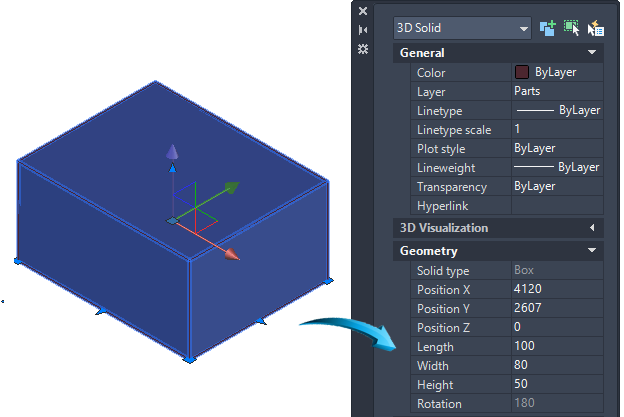
Updating the geometry of a box using the Properties palette
The properties of all objects in the editor can be viewed and modified using the Properties palette, including text, dimensions, hatch features and all line and circle geometry.
To select and modify an object using the grips, select the object to attach the grips, then right-click anywhere in the editor and select Properties from the context menu.
See Also
Grips are useful for modifying dimensions and text and can be used to swiftly move blocks and other compound objectsGroups and Blocks around the editor.
Grid Display
Status Bar | Grid
A regular series of vertical and horizontal lines can be displayed in the editor by creating a Grid.
The Grid Snap mode works by attaching the cursor onto each grid intersection.
The Grid snap mode will function even when the grid is not displayed.
The pointing device constrains to the grid intervals, when the Grid Snap Mode is activated.
Grid lines can be adjusted so they contain major and minor grid line intervals, shown below.
When the Grid Snap mode is inactive, the grid display remains visible, almost as an grid-paper underlay.
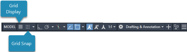
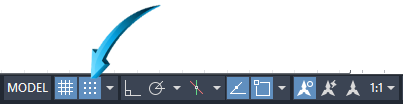
The Grid Display and the Grid Snap modes are activated and deactivated using the icons on the Status bar shown below.
Grid Settings
The display of the Grid is controlled by the Grid Settings option, accessed by right-clicking on the Grid Display icon shown above and selecting the Grid Settings option.
Grid intervals and settings can be applied here, similar to the illustration below. In this example, the X-Y grid has been set to a spacing of 20 with major grid lines displayed at intervals of 5.
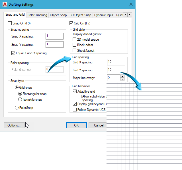
Applying the grid settings of X-Y Grid Setting of 20 with major grid intervals set to 5
Grid Snap
A grid snap mode can be activated so that the cursor snaps to the intersections or the grid points of the displayed grid.
The grid snap is not dependent on the display of the grid. The grid display can be switched off, but if the grid snap is activated, the cursor will still snap to the grid intersections.
The Grid Snap tab is shown below, or the F9 function key can be used to activate and deactivate the grid snap mode.
Activating/Deactivating Grid snap mode
Object Snap Modes
Status Bar | Object Snap
Using Object Snap Modes is the method of creating precision input into the editor by defining specific points of geometry on an object.
By selecting the Object Snap icon in the Status bar, all selected object snap modes are activated or deactivated. In the example below, snap modes are shown activated.
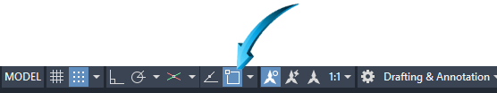
Activating/Deactivating Object Snap Modes
Activating/Deactivating Object Snaps
To activate or deactivate a specific object snap, select the downward arrow shown by the pointer below. In the example below, the Endpoint, Center, Intersection and Extension object snaps are activated.
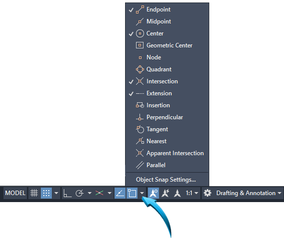
Selecting or deselecting Object Snap modes
Points of Geometry
Most objects have multiple snap modes, shown in the illustrations, below. The keyboard TAB key is used to cycle through the available snap modes until the preferred auto snap marker is displayed.
Object Snaps on Lines
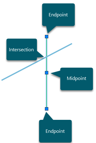
Snap modes on line objects
Object Snaps on Arcs
Quadrant is on the polar axis points of a circle. Center snaps to the center of arcs and circles.
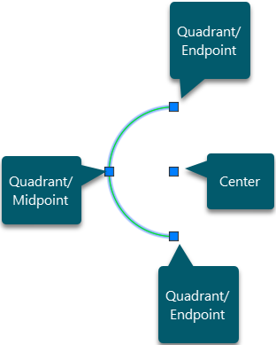
Snap modes on arcs
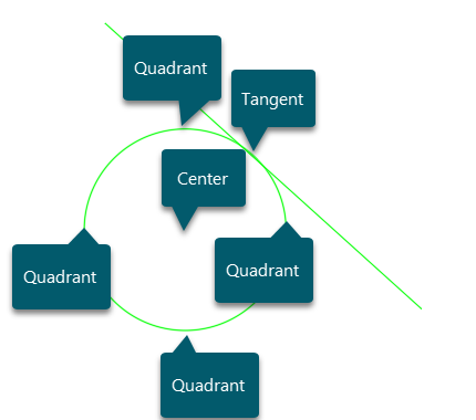
Snap Modes on Circles
Quadrant snaps to the polar points of a circle. Center snaps to the centerpoint of a circle. Tangent snaps to the tangential point of a circle and another entity such as a line or circle.
Additional Snap Points
The Nearest snap mode finds the nearest non-specific point on a sketch object. The Perpendicular snap is used to connect to the horizontal line at 90º in the illustration below.
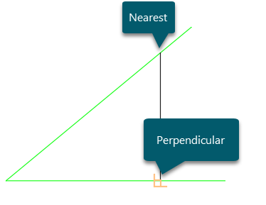
Nearest & Perpendicular snaps
Extension
Extension snap is the projected orthogonal point, usually projected from an endpoint.
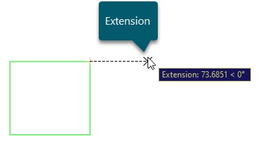
Find a projected extension point
Geometric Center
This snap finds the center of a simple 2D polygonal shape. In the example below, the geometric center is found at the 'center' of the rectangle.
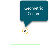
Find the geometric center of a rectangle
This object snap is also used to find the geometric center of a complex polygonal shape, shown below.
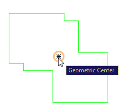
Finding the geometric center of a polygonal shape
Using the TAB key TO CYCLE BETWEEN SNAPS
Multiple snap modes can be activated simultaneously and the keyboard TAB key used to cycle between the available options.
In the example below, the line is started from the point on the angled line shown by the pointer. The horizontal line has 4 available object snap points.
The keyboard TAB key is used to cycle between the available options, shown below.
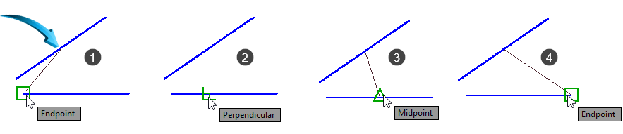
Using the keyboard TAB key to find the available object snap options
Take Note
The snap modes in the illustration above must be activated. Select the Osnap tab in the Status bar or use the function key F3. Check each snap mode to activate.
Aperture Size
The aperture is the target zone at the intersection of the crosshairs. For a point of geometry such as an endpoint to be correctly targeted, it must fall within the range of the aperture. This applies to either a crosshair or cursor setting.
The Aperture size is adjusted by right-clicking in the editor and selecting Options > Drafting, shown by the pointer below.
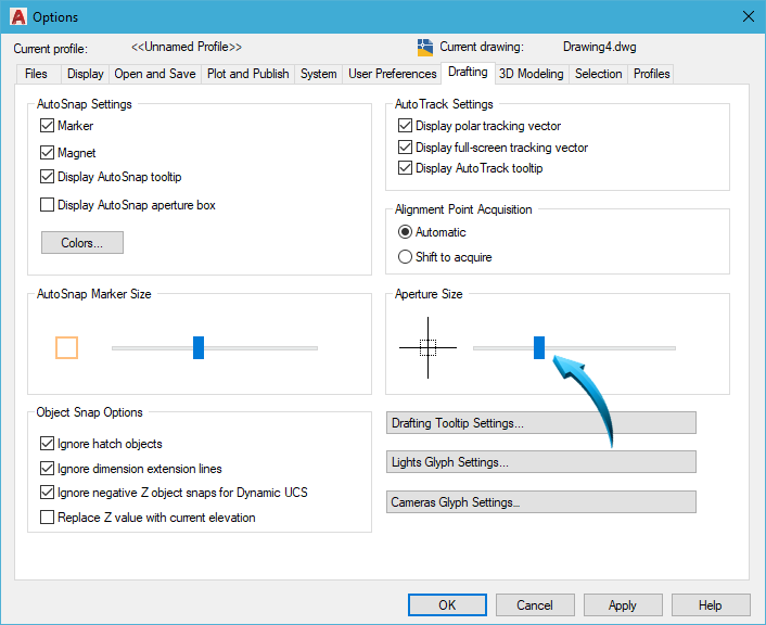
Setting the aperture size
Auto Snap Marker Size
The Auto Snap Marker is the magnetic attraction point of an object snap mode when a selected snap mode is within range. In the example below, the Auto Snap Marker is shown for Endpoint.
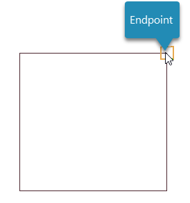
Showing the Auto Snap marker for Endpoint
The size of the Auto Snap Marker is adjusted by right-clicking in the editor and selecting Options > Drafting, shown by the pointer below.
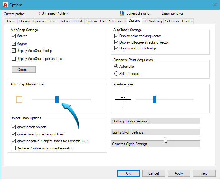
Setting the AutoSnap Marker Size
Object Snap Tracking | Show Reference Lines
This feature provides a magnetic tracking line to an intended object snap mode. The Object Snap Tracking setting is activated from the Status bar below.
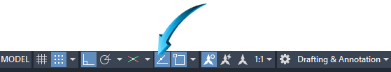
Activating the Object Snap Tracking/Show Reference Line option
In the example below, the line is drawn from top to bottom and is shown tracking to the endpoint at the bottom right corner of the rectangle.
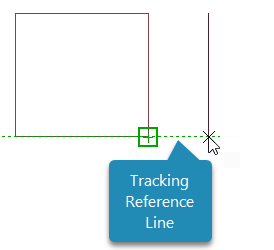
Line tracking to endpoint (corner vertex) of the rectangle
Drawing Units
The units of precision defines the decimal point precision (for metric) units and the number of places of accuracy after the decimal point.
eXAMPLE
The metric unit of precision will be adjusted in the resident drawing.
Input units into the command line and press enter. Change the Length precision to 0.0 shown below by point 1 and repeat this for the Angle decimal degree precision, shown by point 2 below.
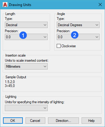
Setting the units of precision for Length and Angle
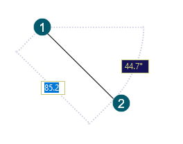
In the example below, it can be observed how the decimal precision has been adjusted to display one decimal point precision on both length and angle input.
take Note :
Changing the precision of the decimal units does not automatically adjust the precision of the dimension decimal places. This feature is controlled through the Dimension Settings Drafting & Annotation | Home | Annotate | Dimensionspalette.
 Back to Top