AutoCAD User Interface
The User Interface
The graphical user interface of software is a fully customizable interface which controls the appearance and performance of fixed and dynamic objects such as menu tabs, ribbons, panels and toolbars.
This is referred to as the Workspace, and menu interfaces can be adapted to a particular work application such as Drafting & Annotation, 3D Basics, 3D Modeling etc.
Menu interfaces can be adapted to a particular work application using the menu tab shown below.
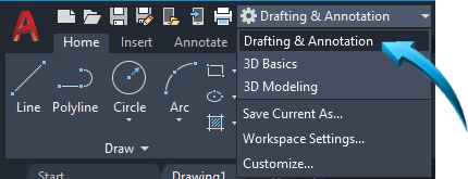
Applying the AutoCAD Drafting & Annotation Menu
Additional Resources
The wORKSPACE
This is the area where the model is drawn and dimensioned at full scale.
The workspace is also referred to as the editor or the Model Workspace.
The workspace is of infinite size, shrinking or expanding to accommodate the sketch or model.
It is not necessary to create a pre-defined drawing area in the workspace. Just start your design, and draw using full scale measurements.
The Model tab at the base of the workspace is active when the workspace is in Model Space layout.
The background color of the workspace can be changed by right-clicking and selecting Options > Display > Colors.
Once the model is drawn and dimensioned in full scale, layouts are created to print the model.
Layouts of the sketch or model are created and inserted into the Paper Space layout for printing or previewing purposes and multiple drawing scales can be used on each layout. Title blocks are inserted into the paper space layouts at full scale.
Workspace Menus
Menus which contain customized layouts for specific tasks are found in the title bar shown below.
These menus are specifically designed to provide easy access to the toolsets necessary to complete specific tasks such as Drafting & Annotation, 3D Modeling etc.
These menus can activated at any time without interrupting the on-screen design or any settings previously activated.
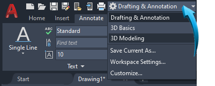
Drafting & Annotation Menu
Canvas Background Color
The background canvas of the workspace can be adapted to each user preference. For the purpose of graphical clarity, all exercises and demonstrations in this learning module are done using a white background.
Right click in the workspace and select Options. Select the Display tab shown by item 1 below, then select Color, shown by item 2.

Setting the color of the background
Select the 2D Model Space from the Context selection, shown by item 3 below, then select Uniform Background from the Interface Element, shown by item 4 below.

Creating a white uniform background
The preferred background color is selected, shown by the arrow above. In this example, a white background is selected.
take note
The white/black colors of layers and will be inverted according to the background canvas of the editor. For example, when the background canvas is set to White and a layer color is designated as white, the drawn objects will be produced using a black outline.
The Menu Interface
Menu tabs, ribbons, panels & toolbars
Toolbars, Menus and Ribbons contain groups of associated tools and commands. The editor can be customized to display any number of Toolbars and Panels.
Toolbars
Toolbars are movable groups of commands which can be seated at the edges of the editor. They can be moved to specific locations using the perforated edge, shown below.
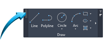
Moving a toolbar or panel using the perforated edge
Toolbars can either be introduced into the editor as docked (fixed against the edge of the editor) or floating, where the perforated edge of the toolbar can be used to move the toolbar to different locations in the editor.
Palettes
View | Palettes
Palettes are specific consoles where associated tools can be displayed. Below is an example of the Layer palette.

Layer Properties Palette
Palettes can be floatingPlaced randomly in the workspace, usually temporarily., dockedMoved to a more convenient location at the edge of the editor. or conveniently structured into accordion-like panels which are docked at the edge of the editor. Multiple palettes can be stacked at the edge of the workspace, then expanded when required.
A floating palette is moved by long-pressing onto the title bar shown by the arrow below, then docked at the preferred location at the edge of the editor.
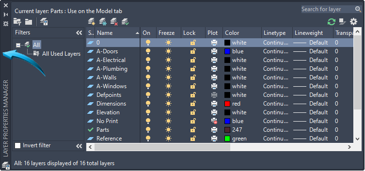
Moving the Layer Properties palette
In the example below, the QuickCalcView > Palettes > Quick Calculator palette is docked at the edge of the editor and is expanded by selecting the title bar shown by the arrow below. The Layer Properties palette is shown below the QuickCalc palette.
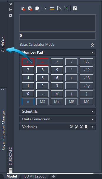
The QuickCalc palette docked at the left edge of the editor
Ribbons & panels
A ribbon is a panel of similar commands grouped for convenience and can be dragged into the editor by long-pressing onto the panel name, shown as item 1 below, then dragging the panel into the editor.

The selected panel is removed from the ribbon and seated in the editor by dragging the panel, shown below.
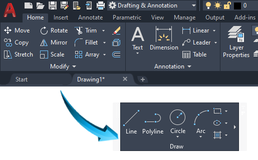
Dragging a panel into the editor
Any panel inserted into the editor can be moved around the workspace by long-pressing the perforated edge, shown below and dragging the panel to a new location in the editor.

Moving a panel around the editor
Additional tools are frequently found by expanding the panel, shown below.

Expanding the panel
The panel is restored to its original position in the ribbon by selecting Return Panels to Ribbon, shown below.
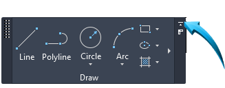
Restoring a panel to the ribbon
Menu Tabs
Menu tabs are the names of the pull down menus located at the top edge of the editor, shown below. Menu tabs can be added or removed from the pull down menu by right clicking into any panel and selecting Show Tabs.

Pull down menu tabs
In this example, additional menu tabs are added by right-clicking in any panel, shown by point 1 below, and selecting Show Tabs. A new menu item can be selected from the unchecked list. In the example below, the 3D Tools menu tab is selected, shown by point 2.
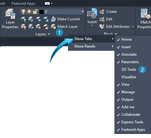
Selecting a new menu tab
The 3D Tools menu tab is added to the pull down menus, shown below.

Adding the 3D Tools menu tab to the pull down menu
The Command Line
The Command Line is the interactive area at the base of the editor where a command or instruction using either the command name or its alias (abbreviated short cut) is input.

Inputting a command into the console
The Command Line is displayed or removed using the keyboard CTRL 9 keyboard keys. When the Command Line console is removed, it is recommended that the Dynamic Input tools be used to create localized input at the cursor.
The Command Line console can be moved using the perforated edge shown by item 1 below, and closed using the button shown by item 2.

Moving the command line console
Inputting a Command into the Command Line Console
Inputting the command name or alias into the Command Line is identical to selecting the instruction from a ribbon panel or menu tab..
Command Line input can also be done at sub-command level, to input the options required for a specific task. For example, the command Circle, shown by item 1 below, can be input as the main command, then TTR(tangent, tangent, radius), shown as item 2 below, as the sub- command.

Inputting the Circle > Tan Tan Radius command into the Command Line
Command Line prompts which occur in square brackets [ ] will always be the default option of a command and pressing the Enter key will accept the current default option.
All commands, sub commands or aliases input into the Command Line console must be followed by the Enter keyboard key.
The Command Line area provides interactive feedback on drawing activity and the scroll or splitter bar can be used to view the command line hierarchy in more detail. This is referred to as the Command History and is found by selecting the arrow shown by the bottom pointer in the illustration below.
In the example below, the Circle command is shown as the most recently input command.
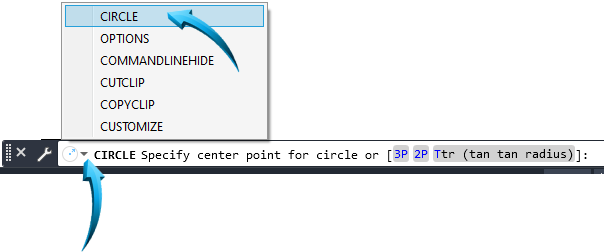
Using the Command Line History
take Note :
Commands can also be entered into the tooltip fields when Dynamic Input is activated.
The Dynamic Input fields can also be used to input information related to the modification function. The Dynamic Input fields are useful for specifying angles and spatial distances during the dynamic modification of the selected objects.
Dynamic input is activated by left-clicking the customization option shown by 3 small horizontal lines at the lower right of the editor and selecting Dynamic Input from the context menu. When Dynamic Input is activated, it is shown in the Status bar, below.

Command Aliases | Keyboard Shortcuts
A Command Alias is a simple one or two letter keyword which is input into the Command Line to activate a command.
A Command Alias is usually an abbreviated name for the command which does not contain spaces and can either be input in capital or non-capitalized letters.
Command Aliases are referred to as keyboard shortcuts and a selection of the more commonly used aliases are shown below.
| Command Alias | Command |
| 3A | 3DARRAY |
| 3DO | 3DORBIT |
| 3DP | 3DPRINT |
| 3DW | 3DWALK |
| 3F | 3DFACE |
| 3M | 3DMOVE |
| 3P | 3DPOLY |
| 3R | 3DROTATE |
| 3S | 3DSCALE |
| A | ARC |
| AC | ACTION |
| ADC | ADCENTER |
| AA | AREA |
| AL | ALIGN |
| 3AL | 3DALIGN |
| AP | APPLOAD |
| AR | ARRAY |
| -AR | -ARRAY |
| ARR | ACTRECORD |
| ARM | ACTUSERMESSAGE |
| -ARM | -ACTUSERMESSAGE |
| ARU | ACTUSERINPUT |
| ARS | ACTSTOP |
| -ARS | -ACTSTOP |
| ATI | ATTIPEDIT |
| ATT | ATTDEF |
| -ATT | -ATTDEF |
| ATE | ATTEDIT |
| -ATE | -ATTEDIT |
| ATTE | -ATTEDIT |
| B | BLOCK |
| -B | -BLOCK |
| BC | BCLOSE |
| BE | BEDIT |
| BH | HATCH |
| BO | BOUNDARY |
| -BO | -BOUNDARY |
| BR | BREAK |
| BS | BSAVE |
| BVS | BVSTATE |
| C | CIRCLE |
| CAM | CAMERA |
| CBAR | CONSTRAINTBAR |
| CH | PROPERTIES |
| -CH | CHANGE |
| CHA | CHAMFER |
| CHK | CHECKSTANDARDS |
| CLI | COMMANDLINE |
| COL | COLOR |
| CO | COPY |
| CP | COPY |
| CT | CTABLESTYLE |
| CUBE | NAVVCUBE |
| CYL | CYLINDER |
| D | DIMSTYLE |
| DAL | DIMALIGNED |
| DAN | DIMANGULAR |
| DAR | DIMARC |
| JOG | DIMJOGGED |
| DBA | DIMBASELINE |
| DBC | DBCONNECT |
| DC | ADCENTER |
| DCE | DIMCENTER |
| DCO | DIMCONTINUE |
| DCON | DIMCONSTRAINT |
| DDA | DIMDISASSOCIATE |
| DDI | DIMDIAMETER |
| DED | DIMEDIT |
| DI | DIST |
| DIV | DIVIDE |
| DJL | DIMJOGLINE |
| DJO | DIMJOGGED |
| DL | DATALINK |
| DLI | DIMLINEAR |
| DLU | DATALINKUPDATE |
| DO | DONUT |
| DOR | DIMORDINATE |
| DOV | DIMOVERRIDE |
| DR | DRAWORDER |
| DRA | DIMRADIUS |
| DRE | DIMREASSOCIATE |
| DRM | DRAWINGRECOVERY |
| DS | DSETTINGS |
| DST | DIMSTYLE |
| DT | TEXT |
| DV | DVIEW |
| DX | DATAEXTRACTION |
| E | ERASE |
| ED | DDEDIT |
| EL | ELLIPSE |
| ER | EXTERNALREFERENCES |
| ESHOT | EDITSHOT |
| EX | EXTEND |
| EXIT | QUIT |
| EXP | EXPORT |
| EXT | EXTRUDE |
| F | FILLET |
| FI | FILTER |
| FSHOT | FLATSHOT |
| G | GROUP |
| -G | -GROUP |
| GCON | GEOCONSTRAINT |
| GD | GRADIENT |
| GEO | GEOGRAPHICLOCATION |
| GR | DDGRIPS |
| H | HATCH |
| -H | -HATCH |
| HB | HATCHTOBACK |
| HE | HATCHEDIT |
| HI | HIDE |
| I | INSERT |
| -I | -INSERT |
| IAD | IMAGEADJUST |
| IAT | IMAGEATTACH |
| ICL | IMAGECLIP |
| IM | IMAGE |
| -IM | -IMAGE |
| IMP | IMPORT |
| IN | INTERSECT |
| INF | INTERFERE |
| IO | INSERTOBJ |
| J | JOIN |
| L | LINE |
| LA | LAYER |
| -LA | -LAYER |
| LAS | LAYERSTATE |
| LE | QLEADER |
| LEN | LENGTHEN |
| LESS | MESHSMOOTHLESS |
| LI | LIST |
| LMAN | LAYERSTATE |
| LO | -LAYOUT |
| LS | LIST |
| LT | LINETYPE |
| -LT | -LINETYPE |
| LTYPE | LINETYPE |
| -LTYPE | -LINETYPE |
| LTS | LTSCALE |
| LW | LWEIGHT |
| M | MOVE |
| MA | MATCHPROP |
| MAT | MATERIALS |
| ME | MEASURE |
| MEA | MEASUREREGION |
| MI | MIRROR |
| ML | MLINE |
| MLA | MLEADERALIGN |
| MLC | MLEADERCOLLECT |
| MLD | MLEADER |
| MLE | MLEADEREDIT |
| MLS | MLEADERSTYLE |
| MO | PROPERTIES |
| MORE | MESHSMOOTHMORE |
| MS | MSPACE |
| MSM | MARKUP |
| MT | MTEXT |
| MV | MVIEW |
| NORTH | GEOGRAPHICLOCATION |
| NSHOT | NEWSHOT |
| NVIEW | NEWVIEW |
| O | OFFSET |
| OP | OPTIONS |
| ORBIT | 3DORBIT |
| OS | OSNAP |
| -OS | -OSNAP |
| P | PAN |
| -P | -PAN |
| PA | PASTESPEC |
| PAR | PARAMETERS |
| -PAR | -PARAMETERS |
| PARAM | BPARAMETER |
| PATCH | SURFPATCH |
| PC | POINTCLOUD |
| PCATTACH | POINTCLOUDATTACH |
| PCINDEX | POINTCLOUDINDEX |
| PE | PEDIT |
| PL | PLINE |
| PO | POINT |
| POFF | HIDEPALETTES |
| POL | POLYGON |
| PON | SHOWPALETTES |
| PR | PROPERTIES |
| PROPS | PROPERTIES |
| PRE | PREVIEW |
| PLOT | |
| PS | PSPACE |
| PSOLID | POLYSOLID |
| PTW | PUBLISHTOWEB |
| PU | PURGE |
| -PU | -PURGE |
| PYR | PYRAMID |
| QC | QUICKCALC |
| QCUI | QUICKCUI |
| QP | QUICKPROPERTIES |
| QVD | QVDDRAWING |
| QVDC | QVDDRAWINGCLOSE |
| QVL | QVLAYOUT |
| QVLC | QVLAYOUTCLOSE |
| R | REDRAW |
| RA | REDRAWALL |
| RC | RENDERCROP |
| RE | REGEN |
| REA | REGENALL |
| REC | RECTANG |
| REG | REGION |
| REN | RENAME |
| -REN | -RENAME |
| REV | REVOLVE |
| RO | ROTATE |
| RP | RENDERPRESETS |
| RPR | RPREF |
| RR | RENDER |
| RW | RENDERWIN |
| S | STRETCH |
| SC | SCALE |
| SCR | SCRIPT |
| SE | DSETTINGS |
| SEC | SECTION |
| SET | SETVAR |
| SHA | SHADEMODE |
| SL | SLICE |
| SN | SNAP |
| SO | SOLID |
| SP | SPELL |
| SPL | SPLINE |
| SPLANE | SECTIONPLANE |
| SPLAY | SEQUENCEPALY |
| SPLIT | MESHSPLIT |
| SPE | SPLINEDIT |
| SSM | SHEETSET |
| ST | STYLE |
| STA | STANDARDS |
| SU | SUBTRACT |
| T | MTEXT |
| -T | -MTEXT |
| TA | TABLET |
| TB | TABLE |
| TEDIT | TEXTEDIT |
| TH | THICKNESS |
| TI | TILEMODE |
| TO | TOOLBAR |
| TOL | TOLERANCE |
| TOR | TORUS |
| TP | TOOLPALETTES |
| TR | TRIM |
| TS | TABLESTYLE |
| UC | UCSMAN |
| UN | UNITS |
| -UN | -UNITS |
| UNHIDE | UNISOLATEOBJECTS |
| UNI | UNION |
| UNISOLATE | UNISOLATEOBJECT |
| V | VIEW |
| -V | -VIEW |
| VGO | VIEWGO |
| VP | DDVPOINT |
| -VP | VPOINT |
| VPLAY | VIEWPLAY |
| VS | VSCURRENT |
| VSM | VISUALSTYLES |
| -VSM | -VISUALSTYLES |
| W | WBLOCK |
| -W | -WBLOCK |
| WE | WEDGE |
| WHEEL | NAVSWHEEL |
| X | EXPLODE |
| XA | XATTACH |
| XB | XBIND |
| -XB | -XBIND |
| XC | XCLIP |
| XL | XLINE |
| XR | XREF |
| -XR | -XREF |
| Z | ZOOM |
| ZEBRA | ANALYSISZEBRA |
The Status Bar

The Status Bar is seated at the lower right corner of the editor and provides quick access to useful settings.
These setting directly affect the functional workspace and provide useful toggle settings for each mode.
Model
This switches the workspace between the Model (drawing and design area) to the Paper (layout) areas of the editor.
Display Drawing Grid
A Drawing Grid provides the display of a matrix on the x-y axis. The size, appearance and behavior of the grid is controlled by right-clicking onto Display Drawing Grid and applying the settings shown below.
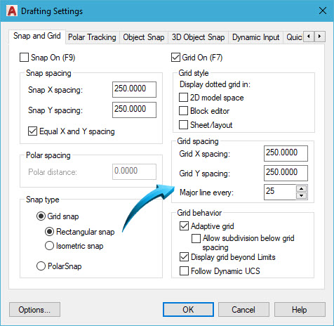
Applying grid settings
Object Snap Modes
This switches the snap modes on or off, over-riding any pre-set snap settings.
Snap modes are accessed by holding down the keyboard SHIFT key and right-clicking in the editor. This is a transparent instruction and the command line is not required to be cleared prior to activating the snap modes shown below.
Snap Settings are controlled by right-clicking onto the Snap Mode tab and selecting the Object Snap tab, shown below.
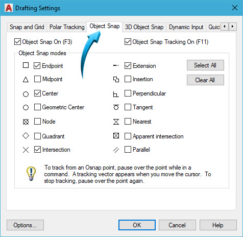
Setting a fixed object snap
Ortho Mode
When Ortho mode is activated in the status bar or by using the (fn) F8 function key, the movement of the cursor is locked into strictly polar angle movement (0, 90, 180, 360 degree movement)
IsoDraft
This switches the orientation of the crosshair to a view dynamic suitable for isometric drawing.
Object Snap Tracking
When activated, a magnetic reference line is used to track between start and destination points.
Dynamic Input
Input fields are the data fields into which spatial information and commands are input, similar to the illustrations below.
When the Dynamic Input feature is activated, command instructions are shifted from the command line at the bottom of the editor to a local point defined by the cursor/crosshair position. This keeps the attention centered in the editor and commands, sub commands and spatial information can be input here.
The Dynamic Input fields can be displayed or concealed by activating the Dynamic Input tab in the status bar at the bottom right of the editor, shown below.

Activating Dynamic Input
In the example below, the command L was input to activate the Line command. A start point was indicated, shown by point 1, then the dynamic input at the cursor can either be used to input length and angle coordinates. Until the coordinates are input into the data fields, a visual representation of the spatial coordinates of the line are shown in the dynamic input fields.
Using the TAB key during Dynamic Input
The data fields, shown below as the Length and Angle fields are accessed using the keyboard TAB key. The data is input into the coordinate fields, followed by the keyboard ENTER key. After the keyboard ENTER key is pressed, the data field is locked, shown by the orange padlock in the data fields below.
The keyboard TAB key is used to cycle between any data fields displayed at the location of the cursor.
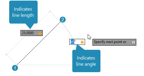
Dynamic Input Fields, inputting length of line and angle
The temporary display of the Dynamic Input interface can be controlled using the (fn) F12 keyboard key/s. This will hide or display the dynamic input without compromising the design.
Customizing the Dynamic Input Fields (Tooltips)
The size and color of the data fields of the dynamic input fields can be adjusted using Options > Drafting > Drafting Tooltip Settings.
Set the size and color preferences of the Tooltip appearance in the dialog box shown below.
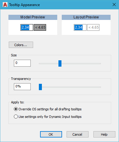
Adjusting the appearance of the tooltips & dynamic input fields
The Input Device
The input device, also referred to as the pointing device provides either a cursor or crosshair input interface and can be adapted to suit user preferences. These may be adjusted at any time during the design session.
The features of the input device can be controlled using Options > Drafting. The Auto Snap Marker, shown by point 1 and the Aperture Size, show by point 2 can be adjusted here.
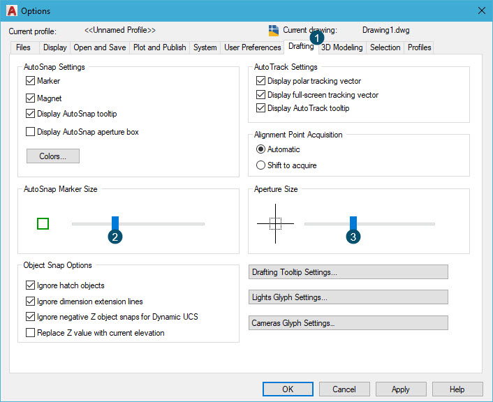
Modifying the Input Device and Aperture Size
The length of the crosshairs can be adjusted using Options > Display, shown by point 2 below.
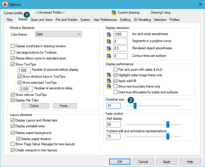
Setting the crosshair size to 15
Right-Click cUSTOMIZATION
The right mouse button can be separately customized using Options > User Preferences and selecting Right-click Customization, shown by point 2 below.
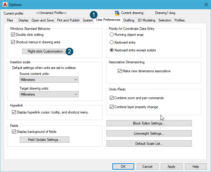
Customizing the right-click mouse button
User preferences are input into the dialog box shown below.

Right-click customization
Zoom & Navigational tools
Zoom Tools
Zoom magnification functions are done by right-clicking in the workspace and selecting the relevant zoom option from the context menu. The Zoom tools work in conjunction with the mouse buttons and wheel, allowing smooth increasing or decreasing of the objects in the workspace.
Example
Right click in the workspace and select Zoom. To increase the magnification, long-press the left mouse button and move the mouse in an upward direction. To decrease the magnification, long-press the left mouse button and move the mouse in an downward direction.
To define a specific area to zoom, right click in the workspace and select Zoom Window. Place a rectangular frame around the area to zoom to increase the magnification to its maximum. To return the zoom to the original, right click and select Zoom Extents. This zooms the workspace to the extents of the objects.
The Zoom command is a transparent command; it can be used within other commands without interrupting the command sequence. The Zoom command is also an intuitive command, allowing the mouse to create an increased or decreased magnification centered around the position of the cursor simply by positioning the cursor in the intended center of the zoom and rolling the mouse wheel upwards or downwards to increase or decrease the zoom.
Pan Tools
The Pan facility allows mobility of the objects in the workspace by long-pressing the mouse wheel and visually sliding the objects around the workspace. The mouse wheel can be used both to increase and decrease the zoom magnification by rolling the mouse wheel up or down, or by long-pressing the wheel and directing the movement of the objects using the mouse.
Scroll Bars
Horizontal and vertical scroll bars can be displayed at the right side and the base of the editor by enabling this setting in the Options palette. Right click in the workspace and select Options > Display > Enable scroll bars in the drawing.
ViewCube & compass
Drafting & Annotation | View | Viewpoint Tools | ViewCube
The ViewCube is a dynamic icon at the top right of the editor which displays and adapts to world or user-defined 3 dimensional views. It can be used to adjust the viewing plane of the design.
In the illustration below, the ViewCube is shown from top/plan view below left and isometric south east view, below right.
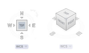
Displaying the ViewCube in plan and isometric view
In the example below, the design in the editor and the ViewCube represent the model in Top view.

Model and ViewCube represent Top view
The ViewCube is responsive; by selecting a viewpoint position on the cube, similar to that shown below, the viewing plane in the editor responds accordingly. In the example below, the isometric south east viewpoint is selected on the ViewCube.
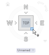
Selecting the isometric south east viewpoint on the ViewCube
The view in the editor and the ViewCube respond to the newly selected isometric viewpoint, shown below.
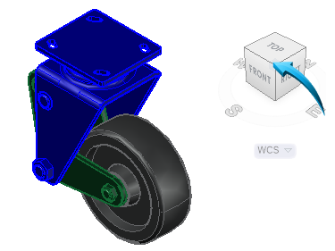
Viewpoint turned to isometric south east
The Compass
Drafting & Annotation | View | Viewpoint Tools | ViewCube
The compass provides a dynamic rotation of the viewpoint, of the model, responding to the position selected on the compass wheel.
In the example below, the viewpoint rotation is achieved by long-pressing onto the compass wheel, shown by the right pointer and dragging the wheel in the desired directional orbit. A pivot sphere is shown at the gravitational center of the model, shown by the left pointer below.

Using the Compass wheel to pivot the model
Take Note
By holding down the keyboard SHIFT key and long-pressing the mouse wheel, the mouse can be moved around the workspace to adjust the viewpoint.
The Navigation Bar
Drafting & Annotation | View | Viewport Tools | Navigation Bar
The Navigation Bar, shown at the right edge of the editor when activated, provides an interactive tool for creating activity in the editor.
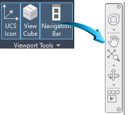
Displaying the Navigational tools
Full Navigation Wheel
Drafting & Annotation | View | Viewport Tools | Navigation Bar
This provides a floating navigational wheel from which multiple viewing tools can be accessed.
Each option of the navigational wheel is activated by long-pressing on the required command. For example, to orbit the model around the editor, select the full navigational wheel, then long-press onto the Orbit tool shown below. Orbit the model with the left mouse button still long-pressed.
To end the command, release the mouse button.
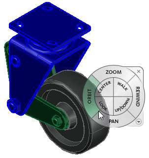
Using the floating navigational wheel
UCS icon
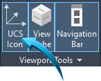
Drafting & Annotation | View | Viewport Tools | Navigation Bar
The UCSUser Coordinate System icon shown by the X-Y axis in the lower left corner of the editor is used to define the orientation of the X-Y-Z axes in a three dimensional plane. When viewed in a 2D plane, it is represented by the display of the X-Y axis only, shown below left.

UCS Icon displayed in the editor in 2D mode (1) and 3D mode (2)
The ViewCube, Navigation Bar and the UCS icon can be displayed or concealed using any of the default workspace menus such as Drafting & Annotation, 3D Basics or 3D Modeling and selecting View > Viewpoint Tools.
Take Note
The Options dialog box discussed in this Session can be accessed by right-clicking in the editor and selecting Options from the context menu. It is also found by selecting the application icon shown at the top left of the editor, below, and selecting Options
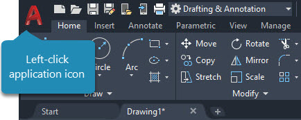
Right click application icon for Options


